2015年1月20日星期二
Benefits Of Sfp+ Transceiver And Dwdm
One of the main benefits of fiber optic transceiver is that it offers a large number of ports per card for a 10-Gbit/sec light transceiver unit. Considering thermal factors, each one of the board would provide maximum ports. In comparison to Gigabit optical Ethernet transceiver module, this transceiver module offers higher port density.
The next advantage of using the SFP+ transceiver is its potential for reducing costs without affecting relative performance. It offers cost reduction due to two factors. The first is the smaller area that eliminates the need for more amount of costly silicon, and the second is that the basic design helps reduce costs of production. Thus, one can have an inexpensive but high-end GB Ethernet transceiver. In fact, the costs are even lower than X2, XFP and XENPAK.
These Transceivers have more compact form compared to XFP and X2, and they can be connected directly with similar type X2, XFP,1000BASE-T SFP module and XENPAK. The transceiver complies with the protocols SFF-8432, SFF-8431 and IEEE802.3ae, and it is a mainstream design.
Dense Wavelength Division Multiplexing or DWDM technology is used for increasing fiber optics capacity resulting in faster data transfers. It would take multiple signals and transmits them forward at different wavelengths concurrently through one fiber. This helps in making the most out of a single fiber, transforming it virtually into several fibers. Currently, the fastest data transmission from the technology has been found to be 400 GB per second.
It can be used for sending 80 wavelengths simultaneously. This means that the technology can be used for converting 1 GB per second capacity into 80 GB per second transmission.
The faster data transfer capabilities of DWDM offer benefits for SONET, ATM and IP transfers. This would help computer systems to operate networks faster and better, overall. This growth in efficiency helps increase data transmission speed at a dramatic level.
The next advantage of the technology is that it avoids the need for laying new fiber because it can help make the most out of the existing fiber. Due to this reason, the technology is not just more convenient but more financially beneficial because laying down new fiber can dramatically increase the costs.
The development of the technology has helped dramatically increase transmission capacity. it is helpful in increasing wavelengths by 2 to 3 times by suppliers. There is no need for improving or restoring the fibers already laid down because it is possible to upgrade links simply through upgrading or reorganizing.
The DWDM fiber network delivers the essential infrastructure required for supporting current and future technologies by offering unlimited bandwidth capacity. The integrated resources offered would help in meeting the ever-increasing telecommunication needs. Thus, the new technologies in the form of the Transceivers and higher-capacity fiber networks enable the telecommunications and other industries to keep up with the ever-increasing demands.

2014年12月31日星期三
SFP Transceiver Module Troubleshooting
SFP
transceiver is a compact, hot-pluggable transceiver module used for
both telecommunication and data communications applications. With the increasing
high speed data transmission demands of people, products, such as SFP+, CFP and
QSFP/QSFP+ etc. have shared the market. Nonetheless, SFPs have still played an
important role in telecommunication and data communication.
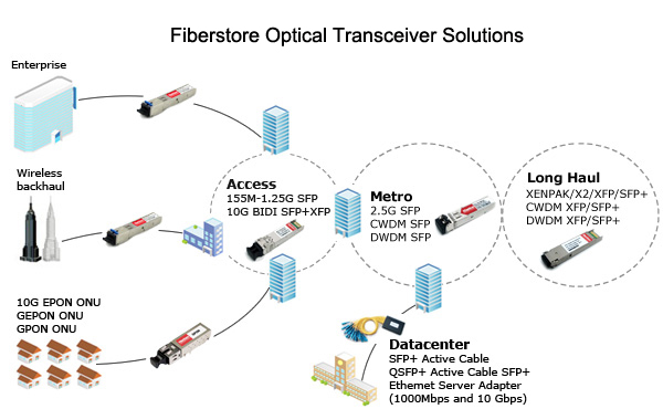
As a widely and commonly used component in data
transmission, due to the incorrect operation or other factors, it is hard to
avoid facing the faults in using SFP, and sometimes even result in a bad
situation and heavy loss. This paper will help you to diagnose the SFP problems
(take cisco
sfp h10gb cu1m for example) and give some resolution tips. I hope
it would be acted as a learning tool and a reference source for both new and
experienced technicians who work in this field.
To diagnose SFP problems, you can get statistics
from the browser interface, the CLI (Command Line Interface) or an SNMP (Simple
Network Management Protocol) workstation. The most common SFP problems include
these aspects:
- Poor performance
- No connectivity
- Corrupted software
- Reduce the cable length to within the recommended distances.
- See your SFP module documentation for cabling guidelines.
No
connectivity Possible
Cause: This problem is more likely related to cabling. Using
incorrect or bad cable, or incorrect cable wiring, or STP (Shielded Twisted
Pair) checking for possible loops may probably lead to this problem. Resolution:
- Verify the pinouts are correct for the proper application of cables.
- Replace the cable with a tested good cable.
- Wait 30 seconds for the port LED to turn green.
Corrupted
software The corrupted software here we mentioned include the
following three situations. 1.The port is placed in error-disabled state
after SFP is inserted. Possible
Cause: This problem is usually caused by bad or
non-Cisco-approved SFP module(ie. the incompatible SFP). Resolution: Remove the SFP module
from the switch and replace it with a Cisco-approved module. Use the irrdisable
recovery cause GBIC-invalid global configuration command to verify the port
status, and enter a time interval to recover from the error-disable state. The
best advice is to use the Cisco original SFP or 100% compatible SFP (If you
decide to use a third-party SFP, please ensure that your supplier is assured)
that is adapted to the switch.
2.Device does not recognize the SFP
module. Possible Cause:
This problem is generally related to the qsfp
4x10g aoc7m installation. Situations, such as SFP is installed
upside dowm or does not snap into the slot can cause this problem. Resolution:
- Verify that the SFP module is not installed upside down.
- Remove the SFP module. Inspect for physical damage to the connector, the module, and the module slot.
- Replace the SFP module with a known good SFP module.
Some common error
message of Cisco Switch When Using With SFP Module Error Message: Transceiver module
inserted in port Explanation: The online insertion
and removal (OIR) facility detected a newly inserted transceiver module for the
interface specified in the error message.
Error
Message: INIT_FAILURE: Detected for transceiver module in port,
module disabled Explanation:An initialization failure
occurred for the transceiver module for the interface specified in the error
message. This condition could be caused by software, firmware, or hardware
problem. As a result of the error, the module is disabled.
Recommended
Action: Try reseating the module. Hardware replacement should
not occur first occurrence. Before requesting hardware replacement, review
troubleshooting logs with a technical support representative.
Error
Message: NOT_IDENTIFIED: Detected for transceiver module in %s,
module disabled Explanation:
The transceiver module for the interface specified in the error message could
not be identified and may not be compatible with the interface. The transceiver
module specified in the error message contains a transceiver code which could
not be correctly interpreted. As a result of the error, the module is
disabled.
Recommended
Action: Replace the module with a compatible transceiver.
Error
Message: UNSUPPORTED-TRANCEIVER: Unsupported SFP transceiver
found on board. Warranty/support may void Explanation: The transceiver
module for the interface specified in the error message is not a Cisco supported
module. As a result of the error, the module is disabled. When Cisco determines
that a fault or defect can be traced to the use of third-party transceivers
installed by a customer or reseller, then, at Cisco's discretion, Cisco may
withhold support under warranty or a Cisco support program. In the course of
providing support for a Cisco networking product Cisco might require that the
end user install Cisco transceivers if Cisco determines that removing
third-party parts will assist Cisco in diagnosing the cause of a support issue.
Recommended Action:
None.
2014年12月29日星期一
Title Tips For Fiber Optic Transceiver Installation
Common Faults Caused by Incorrect Installation
1. Contamination
The most common source of contaminants in the optical bores is debris picked up on the ferrules of the optical connectors. Using an alcohol swab or lint-free absorbent wipes to clean the ferrules of the opticall connector is very necessary. Figure 1 shows the comparison between a normal fiber optic transceiver and a contaminated transceiver. Figure 1 and figure 2 in the following show us the common case of this situation. You can clearly see the white contamination with naked eyes through the comparison of the normal and fault transceiver in figure 1 while figure 2 shows us the phenomenon that the ferrule of optical connectors in the ends of fiber patch cord breaks in the port and make the module fault.
The most common source of contaminants in the optical bores is debris picked up on the ferrules of the optical connectors. Using an alcohol swab or lint-free absorbent wipes to clean the ferrules of the opticall connector is very necessary. Figure 1 shows the comparison between a normal fiber optic transceiver and a contaminated transceiver. Figure 1 and figure 2 in the following show us the common case of this situation. You can clearly see the white contamination with naked eyes through the comparison of the normal and fault transceiver in figure 1 while figure 2 shows us the phenomenon that the ferrule of optical connectors in the ends of fiber patch cord breaks in the port and make the module fault.

Figure 1. The comparison of the normal and fault transceiver

figure 2. The ferrule of optical connectors is broken in the module
In addition, using contaminated fiber patch cord or shoddy fiber patch cord, eventually leads the port of sfp transceiver to be contaminated.
- The unpolished ferrule of non-standard fiber optic connectors in the patch cord end will damage the transceiver modules, as the figure 3 shows.
- Connectors of fiber optic patch cord are full of dust due to the long time unuse and unprotection so that leads the transceiver module ports to be contaminated.
- Using damaged fiber patch cord easily damage the transceiver modules.

Figure 3. Ferrule of fiber optic connector
2. Absence of Conductive Metal
In general, the conductive metal are of a normal and good quality fiber optic transceiver module is glossy. Look at the figure 4, they are both the faulty modules. The left one is lack of conductive metal, while the right is old and not glossy.
In general, the conductive metal are of a normal and good quality fiber optic transceiver module is glossy. Look at the figure 4, they are both the faulty modules. The left one is lack of conductive metal, while the right is old and not glossy.

Figure 4. Absence of conductive metal
3. The Fiber Transceiver Module Is Not Plugged Tightly, Resulting In Optical Signal Transmission Restrictions
When plugged into devices, fiber optic transceiver module must be tightly plugged and the bail clasp must be in place. Otherwise it will easily be interrupted or loosed when there are vibration and impact on the device. The figure 5 shows us the wrong insert-mode.
When plugged into devices, fiber optic transceiver module must be tightly plugged and the bail clasp must be in place. Otherwise it will easily be interrupted or loosed when there are vibration and impact on the device. The figure 5 shows us the wrong insert-mode.

Figure 5. Wrong insert-mode
Tips For Proper Installation
1. Careful Check Before Installation
- Check the conductive metal. A good copper transceiver module usually looks bright, neat (Figure 6)
- Check the bail clasp whether damaged. A damaged bail clasp can easily lead to optical modules in the switch. (Figure 7)
- Check the port surface. A good module end is clean. (Figure 8)

Figure 6. Conductive metal of a good transceiver module

Figure 7. Comparison of good bail clasp and damaged bail clasp

Figure 8. A clean port surface
2. How To Install The Fiber Optic Transceiver Into A Device- Remove the dust plug from the slot chosen for the transceiver.
- Slide the transceiver in the slot until it clicks into place
- Remove the dust plug from the transceiver
Note: Do not remove the dust plug from the transceiver slot if you are not installing the transceiver at this time. The dust plug protects the line card from dust contamination. The dust plug protects the fiber optic port on the transceiver from dust contamination. It should not be removed until you are ready to connect the fiber optic cable.
3. Installation & Removal Of Fiber Optic Patch Cord- Ensure the bail clasp into place before inserting the fiber optic patch cord
- When you insert a fiber optic patch cord, you can hear slight sound “pop” or feel a slight vibration. Check whether it is into place after you plug it into the device. If it can not be removed that means it is installed into place.(Figure 9)

Figure 9. Fiber optic cord Installation
Note: The connector of fiber optic patch cord must install dust caps before plugging into the module. Otherwise it will easily lead to optical modules to be contaminated when it connect to the module. (Figure 10)

Figure 10. Connector of fiber optic patch cord must install dust caps when it is unused
In addition, when you need to remove the 10gbase sr sfp module, you should remove the fiber patch cord first. To be remembered, you should not remove the modules until removing the bail clasp. The correct way to remove module is to loose the bail clasp first and then remove the module through pulling the bail clasp. (Figure 11-12)

Figure 11. Removal of fiber optic patch cord

Figure 12. Removal of fiber optic transceiver module
Fiberstore offers an low cost and high quality option for your requirements. You can find all good fiber optic transceivers, fiber optic patch cords, and other related components in Fiberstore’s website. We also recommended the custom services for your unique demands. More details can visit our official website.
订阅:
博文 (Atom)